| Foredeck framing
This is fairly straightforward. The "dash" frame is mounted as shown in the drawings and glue blocks are used for additional support. The center strong-back is let into the stem with a tapered joint as shown rather than a simple tapered lap which would have left it too thin. To measure and cut the tapers: Place strong-back in position over the frames. Set rear end flush with the dash frame. Mark the rear edge of the stem top cap on the frame. Trace around the forward end of the strong-back on the stem top cap. Taper the strong-back from the mark to the end. Press down on both ends of the strong-back and measure the gap between it and the rear top edge of the stem top cap. In my case this was ~1/4" Mark the rear edge of the stem top cap down from the top for the thickness of the strong-back minus this measurement. Use a handsaw to cut the sides of the tapered notch as well as a couple of cuts in the middle and clean out with a chisel. Once the other notches for the strong-back are cut, it should drop in place with the tapers matching nearly perfectly. The horizontal pipe clamps were pulling the rear most deck frame straight. Do not assume that they are straight. This is your last chance to fix it! |
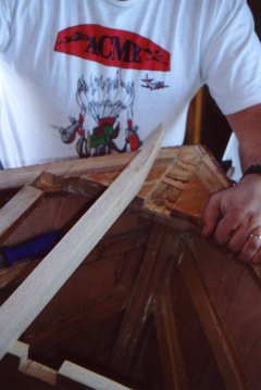
Stem cap to strong back taper
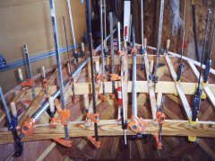
Bow deck frame all clamped up
|
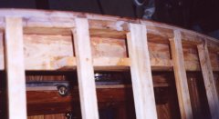
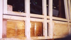
| Rear deck framing
Mount the rear edge of the cockpit as shown in the plans with glue blocks between it and the vertical frame pieces. Temporarily clamp the rear deck supports to the transom. Place the battens in position and mark on the rear deck supports. Mine were angled to provide even spacing. Remove the deck supports and cut the batten notches. Now glue the deck supports in place, while maintaining alignment of the notches. Glue squeeze out and alignment errors are cleaned up with a chisel . This is much easier than trying to cut the notches once the supports are in place and risk damaging the transom. |
 |
| Forward cockpit sides
These are curved and are hard to measure for fit. Measure straight across and add 3/16" to cover length lost due the curvature. Remember that the forward end is beveled. The rear end was nearly square. Use a level to check that the glue blocks are plumb. Screw down the glue blocks prior to trying to bend the side into place or it will probably shift. The clamp pressure alone is not enough to hold with the epoxy acting as a lubricant. |
|
| Rear cockpit sides
Both ends are beveled equally. Measure angle with sliding T bevel. Install blocking, but it will need to be trimmed to fit around frame 2 uprights. |
|
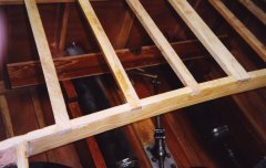
| Ski tow blocking
Forward of the engine hatch, blocking was installed to strengthen the deck and keep it from deforming due to pressure on the ski pylon. Two pieces of wood were added. One at the top which is 14 " long and nearly flush with top of the deck frame. The second is flush with the bottom and 33" long. This makes the section of the frame a box beam and now is very stiff and strong. The top piece should be flush at the ends only to ease fairing. Pre-coat the pieces prior to assembly as getting to the inside of the box will be very difficult when assembled. The inside will get wet due to water coming in through the ski pylon mounting hole. The rear ski tow is mounted at the transom. It will be bolted down through the top horizontal brace of the transom. To provide vertical strength and allow this to be used to lift the boat, an additional block is installed. This point was used to raise the hull when it was inverted and is very strong, but I do not want to risk cracking the horizontal member.
|
Forward skit tow blocking Rear ski tow blocking |
| Next: Hatch Framing | |
| Home | Top |