| Exhaust System
The exhaust system takes up much of the space between the stringers and is the logical starting place for the routing of cables, hoses, etc. The engine has 3.5" exhaust connections which is uncommon. 4" ski boat type silencers are used with angled inlets. Step up adapters are also used to go from 3.5" to 4". The through hull fittings are aluminum trumpets with flappers from Glen-L. Oddly they re specified as 3.5" which is their inner diameter not of the connecting hose which is 4". All of the other exhaust components reference the hose ID which is their OD. Standard wet exhaust hose is used for connections with double stainless steel hose clamps at each connection point. |
|
| Steering and Rudder
This is not really part of the engine, but needs to be done next as this is under the gas tank and is now is the time of easy access. The rudder bracket was set into the stringers as shown, with additional 2x6x6" blocks to provide more bolting area. The rudder was shortened to just fit through the bracket and retaining collar and not touch the gas tank. The tiller arm is run on the port side of the rudder post. Experiment with the motion until a full range of motion is met. Mark the position of the tiller arm on the rudder shaft. Remove the rudder and cut the keyway and file or mill a notch to clear the clamp bolt. Drill the tiller arm at the mark near the end for a 3/8" bolt. The steering cable is run down the center as shown and clamped via an adapter tube and mounting kit. The tube is then clamped in a transom clamp swivel block (p/n???) which is mounted to the strut backing plate. The strut backing plate is drilled and tapped for 5/16" bolts. When drilling the pilot holes make sure they go 1" deeper than the backing plate to allow the tap to go through sufficiently for clean threads. Put 3M5200 or epoxy in the holes to seal them and lock the bolts. The control cable is connected with a pivot assembly, as shown, that came with the mounting kit. The cable is run forward through holes in the floor braces and then up behind what will be the spotters seat and behind the dash frame. A Teleflex Safety QC rotary helm with 19 foot cable was used |
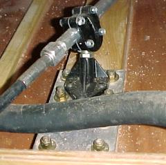
Steering cable mount on strut backer plate |
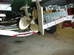
Installed prop and rudder |
|
| Fuel System
The gas tank is designed as a belly tank. There are many more of these available than simple rectangular, and it has a lower profile which should make routing of the gas filler easier. The drawback is that the tank will be cover the rudder shaft. There are three main support pieces for the tank. The bottom is a 2x6. It has end blocks which will keep the tank from shifting sideways. The front and rear supports are angled to match the slope of the bottom. The tank is 30 gallons and should weigh ~200lbs when filled (gas is ~6lb/gal). The tank was fitted with a 3/8" return inlet where a vent fitting had been. The molded in vent fitting is then used for venting. Shut-off valves are placed in both fuel lines to allow for service. Type A fuel hose is used for the fuel lines and the fuel lines are supported with commonly available home copper water pipe supports. 2 tank valves were used in each fuel line. This allows for easy routing of the fuel lines under and then between the stringers. Cap off the now unused port. Each fuel valve was mounted on the outside of the stringers under the rear seat area. |

Fuel valve on stringer. Strap on right is tank hold down. Top black bar is part of the muffler.
|
| Prop Shaft
The prop shaft was too long. Once the prop and prop shaft flange are received, put it in place temporarily. Now mark on the back of the shaft: prop shaft flange rear, prop front, strut rear. Remove everything. The prop shaft flange should go on 2" and the strut to prop spacing should be 1". Measure the distance between the strut and prop marks, subtract 1" and subtract the difference between the actual flange mark and 2". The remaining amount is to be cut off. Place the shaft in a padded vise and cut off. Magnetic padded jaws from Northern Tools are cheap and work well. The Aquamet 22 is extremely hard and also work hardens. Use plenty of cutting fluid and constant pressure. I eased up on the saw pressure for a moment, and the cut work hardened. This wore the teeth off of a bimetal Sawzall blade! If this happens, turn the shaft and start again with a new blade and more cutting fluid. It took over 5 minutes to cut. Use a woodruff key cutter to cut the new prop shaft flange keyway on a milling machine. Take light passes - 0.080" to 0.010" to a total of 0.130" deep. The key had to be filed slightly to be a sliding fit in the keyways. The prop shaft flange had burrs on the inside where the set screws were tapped. File these off and sand with 600 grit paper. You want this to fit together smoothly, otherwise it will bind during assembly as it is a close fit overall. Reassemble everything in the boat and lightly tighten the set screws. Remove the shaft (again!) and file flats where the set screw dug in. If you do not, tightening the set screws will cause a bur on the shaft that may make the flange impossible to remove later. Grease everything and reassemble permanently.
|
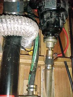
Prop shaft stuffing box. Prop shaft flange is bolted to trans. Orange hose is water to feed prop bearing. Green stripe hose is water feed from sea strainer to engine. Silver hose is blower vent. Yellow is bilge pump, but not connected yet. |
| Next: Electrical | |
| Home | Top |